Posts

Blog 4

Image
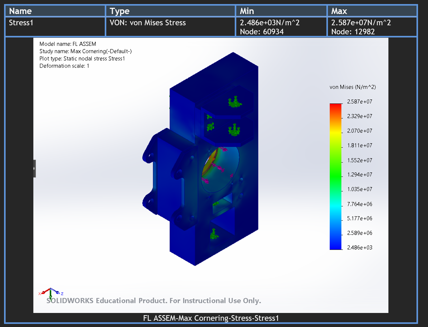
  Progress from November 11th to November 25th, 2023 The team has made significant progress in completing Milestone 2. The team arrived at a finalized design for the front and rear uprights after many iterations using FEA and Topology Optimization. After creating a design that met all of the weight saving and performance goals, the team imported the design into the master assembly of the FSAE car to make sure fitment with all of the other suspension components, shown in Figures 1 and 2 below. Finally, creating a bill of materials is the last step for the team to complete milestone 2.  Figure 1: Front upright integration side view. Figure 2: Front upright integration isometric view. Final Design and its Features The final design of the front uprights incorporates several key features to address the main issues related to suspension geometry and handling. The dimensions of the uprights have been meticulously crafted to achieve optimal suspension geometry parameters, thereby enha...
Blog 3

Image
  Progress from October 28th to November 11th, 2023 In the past two weeks, Team 15 has made significant strides in advancing our project. Notably, we successfully concluded Milestone 1 by finalizing a preliminary CAD design for the front and rear uprights. This accomplishment lays a solid foundation for the subsequent phases of our work. Currently immersed in Milestone 2, the team accomplished the first task by conducting thorough research on the materials for the uprights. This step is pivotal in determining the structural integrity and overall performance of the final product. Table 1 shows the design matrix that the team used to determine the best-suited material for the uprights. Table 1 clearly shows that Aluminum 7075 is the material that fits the needs of the solution the most. Criterion Strength Weight Cost Machinability Overall Score Weight (1-10) 7 9 5 5 cost per bar 2"x4"x12" density g/cm^3 Tensile Strength (MPa) Material Raw score Weighted Score Raw score Wei...

Blog 2

Image
  Blog 2: Team 15 Written by: Leonel Mata, Hisham Hito, Thomas Tran, Melissa Gomez Since the last blog post, team 15 has done extensive research in regard to the uprights for the FSAE car. We have determined that to successfully integrate with the adjacent assemblies, the design of the uprights is governed by different performance-enhancing angles. The main constraints of our project include the suspension geometry and the distribution of loads from accelerating, braking, and cornering. The loads from different driving conditions will impact our material selection and the design of our uprights to resist stress. The suspension geometry will impact our integration into the adjacent assemblies. A visual representation of our constraints is in the table below. Physical constraints Description Value Goal Structural Integrity Minimum Load capacity Pending calculation Factor of Safety  2.5 Maximum allowable deflection 0.5 mm Weight  Maximum allowable weight 3lb - front, 4lb - r...