Blog 4
Progress from November 11th to November 25th, 2023
The team has made significant progress in completing Milestone 2. The team arrived at a finalized design for the front and rear uprights after many iterations using FEA and Topology Optimization. After creating a design that met all of the weight saving and performance goals, the team imported the design into the master assembly of the FSAE car to make sure fitment with all of the other suspension components, shown in Figures 1 and 2 below. Finally, creating a bill of materials is the last step for the team to complete milestone 2.

Figure 1: Front upright integration side view.
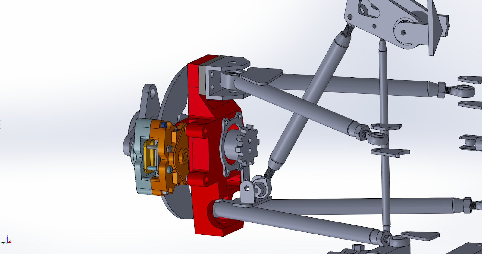
Figure 2: Front upright integration isometric view.
Final Design and its Features
The final design of the front uprights incorporates several key features to address the main issues related to suspension geometry and handling. The dimensions of the uprights have been meticulously crafted to achieve optimal suspension geometry parameters, thereby enhancing overall handling and minimizing driver steering torque. One crucial aspect of the design is its adaptability to different camber settings, allowing for a versatile performance tailored to various driving conditions. Additionally, the material selection and manufacturing processes to be employed ensure a balance between strength and weight, contributing to improved overall vehicle dynamics. The integration of Aluminum 7075 and precision machining techniques further enhances the accuracy and weight reduction of the front uprights, addressing concerns related to suspension integration and unsprung mass reduction. Overall, the final design represents a comprehensive solution that optimizes suspension performance and addresses the main challenges for the FSAE organization.
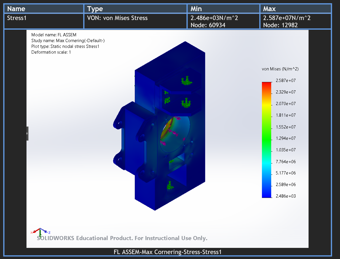
Throughout our iterative design process, we have conducted FEA simulations to measure specifically the weight, maximum displacement, and maximum stress that our upright designs experience to compare them to our goals. Notably, the front uprights experience a maximum stress of 374.5 MPa, shown below in Figure 3, and a maximum deflection of 0.2291 mm in the worst case scenario of maximum braking while weighing 1.81 lbs. The rear uprights experience a maximum stress of 43.55 MPa and a maximum displacement of 0.01862 mm, shown below in Figure 4, during the worst case scenario of maximum acceleration while weighing 2.48 lbs. Both the front and rear upright designs have a max deflection of 0.22 mm, experience marginally less stress than Aluminum 7075’s tensile strength of 572 MPa, and weigh less than 90% of the previous models, all of which surpass our goals of a maximum of 1 mm deflection and at least 10% weight reduction.

Figure 3: Front upright maximum stress (MPa) analysis.
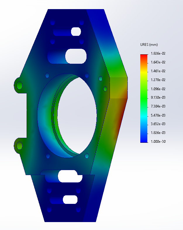
Figure 4: Rear upright maximum displacement (mm) analysis.
Preparations for Capstone II
Team 15 aims to complete Milestone 2 by the end of the fall semester by creating a bill of materials. Once completed, Milestone 3 is planned to take place during the Winter 2023 semester to prepare for the Spring 2024 semester. We will begin by 3D printing a prototype of our finalized designs to present to our stakeholders. We will also physically fit these prototypes into the current FSAE car to make any dimension revisions where necessary. During all of this, the team will communicate with the UH machinist and the machinist that works with FSAE. This communication will make sure that machine constraints are addressed correctly. Once this is complete, we will be confident entering the Spring semester with a revised and finalized design.
Comments
Post a Comment