Blog 3
Progress from October 28th to November 11th, 2023
In the past two weeks, Team 15 has made significant strides in advancing our project. Notably, we successfully concluded Milestone 1 by finalizing a preliminary CAD design for the front and rear uprights. This accomplishment lays a solid foundation for the subsequent phases of our work.
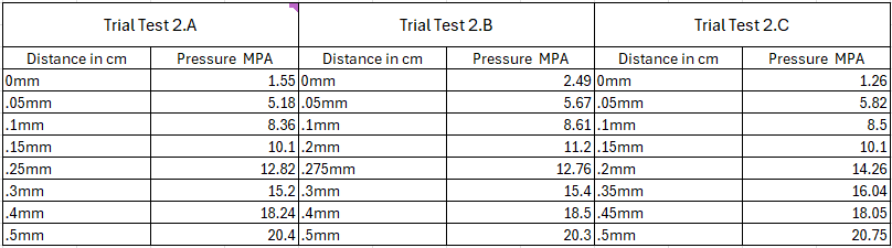
Currently immersed in Milestone 2, the team accomplished the first task by conducting thorough research on the materials for the uprights. This step is pivotal in determining the structural integrity and overall performance of the final product. Table 1 shows the design matrix that the team used to determine the best-suited material for the uprights. Table 1 clearly shows that Aluminum 7075 is the material that fits the needs of the solution the most.
Table 1: design matrix for material selection.
The team has made ample progress in the drafting of different models for the upright. The team has finished 2 template designs for the rear and front uprights and conducted both FEA and Topology Optimization. This has given team 15 great insight into what design changes can be done to reduce weight while still meeting the different design goals. Figure 1 shows the FEA for max cornering on the front left upright template. We can clearly see that the max stress is way below the tensile strength of 572 MPa for aluminum 7075 - T6. Figure 2 shows the displacement plot for the same test and we can see that a max displacement of 5.723e-03 mm is computed. This is way below our design limit of 1 mm, which means that we have a lot of potential to reduce weight using the topology optimization method.
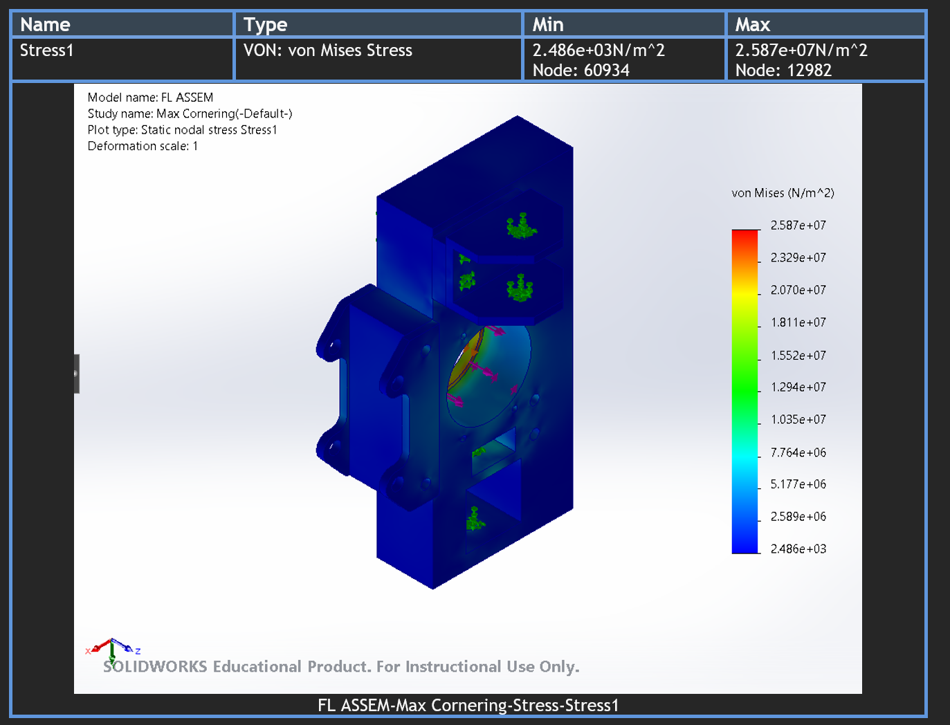
Figure 1: Max Cornering stress plot front upright
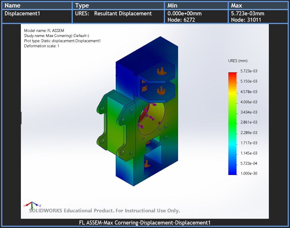
Figure 2: Max cornering displacement plot front upright
Topology optimization was first used in the maximum braking analysis for the front uprights. The team had two tentative designs for the caliper mounts on the uprights. Figure 2 shows a front upright with brake caliper mounts made out of Steel 4340 and the upright structure made out of Aluminum 7075. Figure 3 shows a front upright with the mounts made directly out of the structural aluminum. A Topology optimization study was performed with the best strength-to-weight ratio goal and a target mass reduction of 50%. The result is shown in Figure 4. The team is proud of completing the preliminary FEA for all cases since this will allow for an optimized upright design after all results are considered.
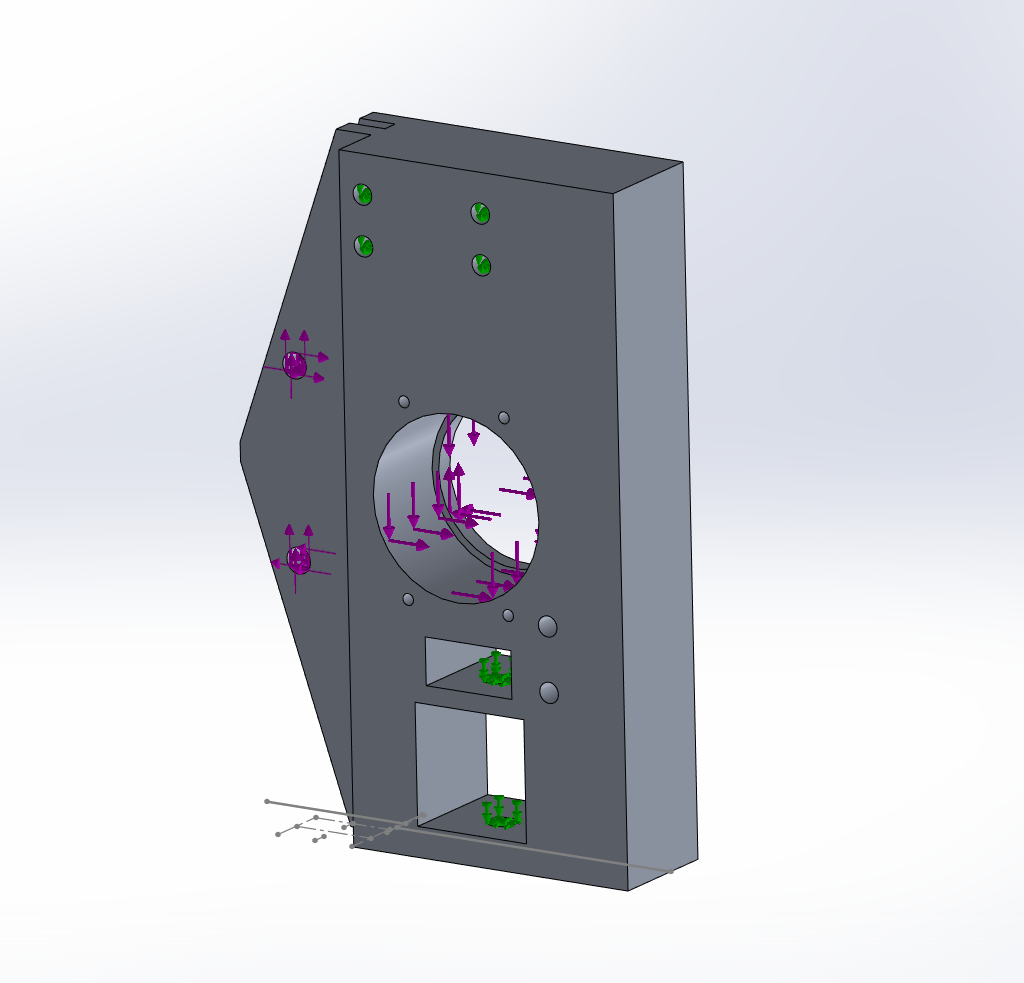
Figure 3: front upright without steel tabs
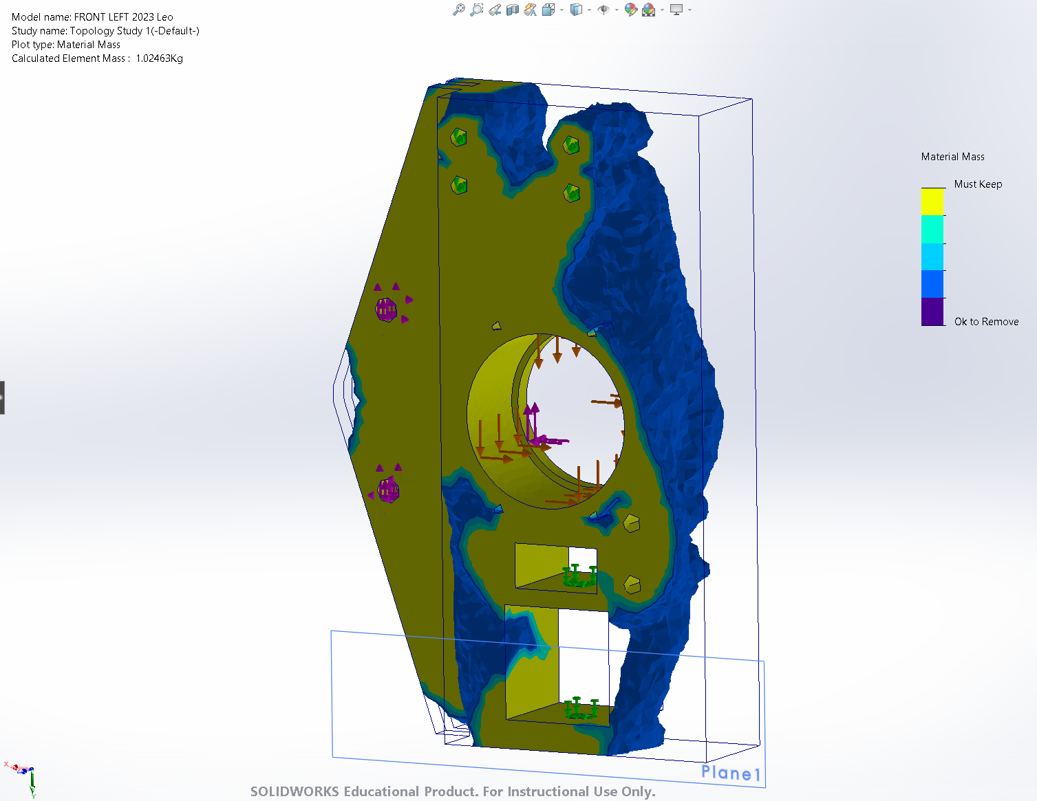
Figure 4: topology optimization using max cornering case on front upright
Future Plans for November 11th to November 25th
As we navigate the upcoming weeks toward the semester's end, our primary objective is to complete Milestone 2 by November 27th. Currently, midway through the milestone, the team is diligently working on FEM and topology optimization, aiming to conclude these tasks by November 25th.
Key tasks within this timeframe include conducting FEM on the rear and front uprights to assess deflection and stress thresholds, as well as executing topology optimization to pinpoint areas for mass reduction. The culmination of Milestone 2 involves a comprehensive examination of the test results, providing the basis for any necessary adjustments, particularly concerning material selection based on considerations such as deflection, fatigue, and cyclic loading.
Diving towards the conclusion of Milestone 2, once the analysis and optimization of the uprights are complete, we hope to integrate all four uprights into the current FSAE master assembly and ensure snug fitment. Once completed, this marks the finalization of our design. We will conclude Milestone 2 and the Fall semester by creating a Bill of Materials.
Future and Current Challenges
The team has encountered problems with the dimensions and being able to draft the correct sizing of the front and rear uprights. To work through this obstacle the team has worked with the suspension team and checked clearances on the master assembly on Onshape. Another challenge the team is facing is whether or not to use the steel tabs for the brake calipers. Having the tabs be part of the structural aluminum allows the team to not have to cut and install the steel tabs while also saving weight and laser-cutting costs. However, they make the upright more difficult to manufacture. The team plans to resolve this issue by discussing with the team’s machinist the different design decisions and arriving at the best solution. One future obstacle that we anticipate is shipping issues with the material the team is planning on using. This is mainly due to the fact that if the materials are not ordered in time, they most likely will be back ordered due to the holidays. In order to prevent this, the team will finalize the Bill of Materials before the end of the semester to place the order before the holidays begin.
Comments
Post a Comment