Blog 2
Blog 2: Team 15
Written by: Leonel Mata, Hisham Hito, Thomas Tran, Melissa Gomez
Since the last blog post, team 15 has done extensive research in regard to the uprights for the FSAE car. We have determined that to successfully integrate with the adjacent assemblies, the design of the uprights is governed by different performance-enhancing angles.
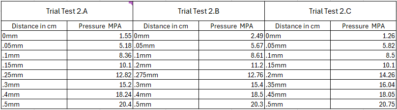
The main constraints of our project include the suspension geometry and the distribution of loads from accelerating, braking, and cornering. The loads from different driving conditions will impact our material selection and the design of our uprights to resist stress. The suspension geometry will impact our integration into the adjacent assemblies. A visual representation of our constraints is in the table below.
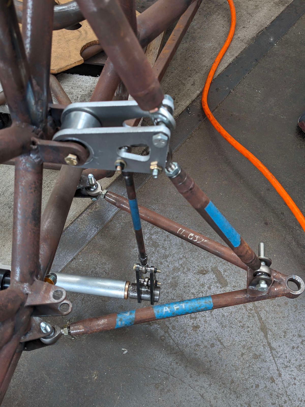
The biggest challenge we expect to face regarding the physical constraints of our problem is the integration of our uprights with the wheel and suspension assemblies. We predict it to be somewhat difficult to design an upright that will connect to all of the pickup points while being able to fit in different positions depending on our goals.
Two angles that we will be heavily focusing on in the design of our uprights are the kingpin inclination angle and the caster angle. The textbook that we have been referencing, titled “Race Car Design '' details two key equations, one specifically for kingpin inclination and the other specifically for caster angle. The following equation is used to determine kingpin inclination:
Using this equation, we can determine the exact position of our upright to obtain a desired kingpin inclination angle of 10°. The following equation is used to determine the caster angle of the uprights:
Similar to the kingpin inclination angle, this equation will be used to determine the exact position that will allow us to minimize the steering torque needed by the driver to less than 10 lbf.
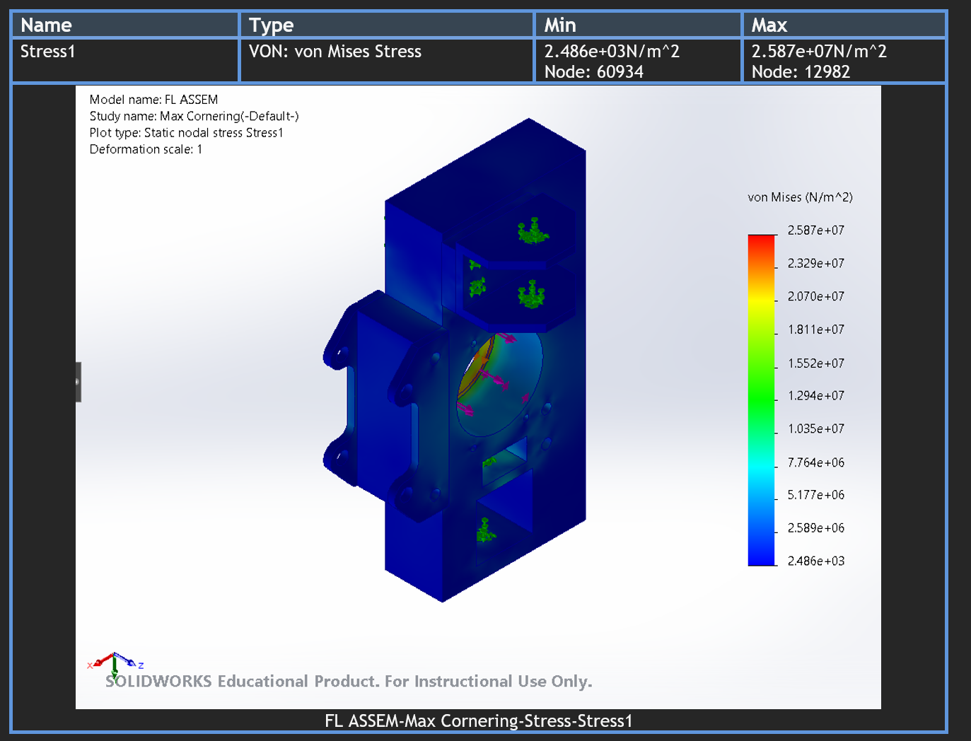
Using force analysis techniques learned in dynamics and solid mechanics, along with an overarching knowledge of vehicle dynamics and loads on different components, we will determine the magnitude of loads acting on the uprights. Drawing inspiration from the upright analysis methods employed in race car design, notably those outlined by Derek Seward, we will meticulously calculate the forces applied to the uprights during various dynamic scenarios.
Subsequently, we will leverage Finite Element Analysis (FEA) to further refine the upright design, ensuring that it not only withstands these calculated forces but also maintains a maximum deflection within the stringent limit of 0.5 mm. We are also aiming to achieve a weight goal of 3 pounds for the front upright and 4 pounds for the rear upright, as well as a safety factor of 2.5. This comprehensive approach combines engineering principles, empirical data, and computational simulations to create an upright assembly that excels in both structural integrity and performance, contributing to the overall success of the race car.
One of the soft challenges the team has begun facing between the last blog post and now is finding a good manufacturer that will be able to provide the necessary and timely availability to create our upright design. Along with that, we are also brainstorming on the material that will be able to meet our technical goals but remain within our budget. This includes looking for a material distributor, and ensuring that the material is shipped and provided in time for the project to be completed.
Some challenges to be considered are the possibility of other sub-teams in FSAE changing or adjusting the size and designs of their components which will then impact the size, positioning, and applicability of our design. We have to take their modifications into consideration through our design process and manufacturing process.
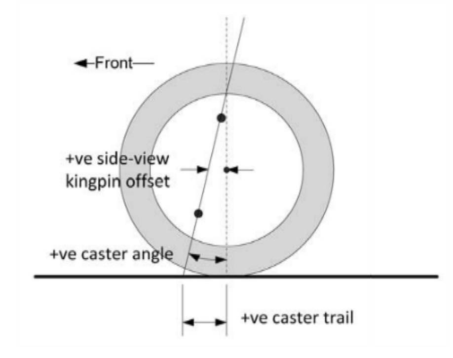
The figure above shows the side view of the wheel. The caster angle is the angle difference between the upper and lower ball joints. The caster angle is what allows the car to self-center. Too little of a caster angle leads to the car oscillating in a weaving fashion, while too large of a caster angle will dominate the driver’s “feel” of steering.

The above figure shows a front view of the upright and brake assembly. The kingpin inclination angle, or steering axis inclination, is the angle between the straight vertical axis and the straight line between the upper and lower ball joints. A smaller steering axis inclination causes a larger scrub radius. This leads to an excessive moment being transmitted to the steering system when encountering an unbalanced force. In driver's terms, this means that the driver would have to strongly resist an unexpected tug at the steering wheel.

UH FSAE 2020 Chassis

UH FSAE 2023-24 Updated Chassis
Comments
Post a Comment