Blog 7
For the work period of March 9 - March 23, what work toward your team's project has been completed?
The team has focused on having everything ready for completing validation once the uprights are done being
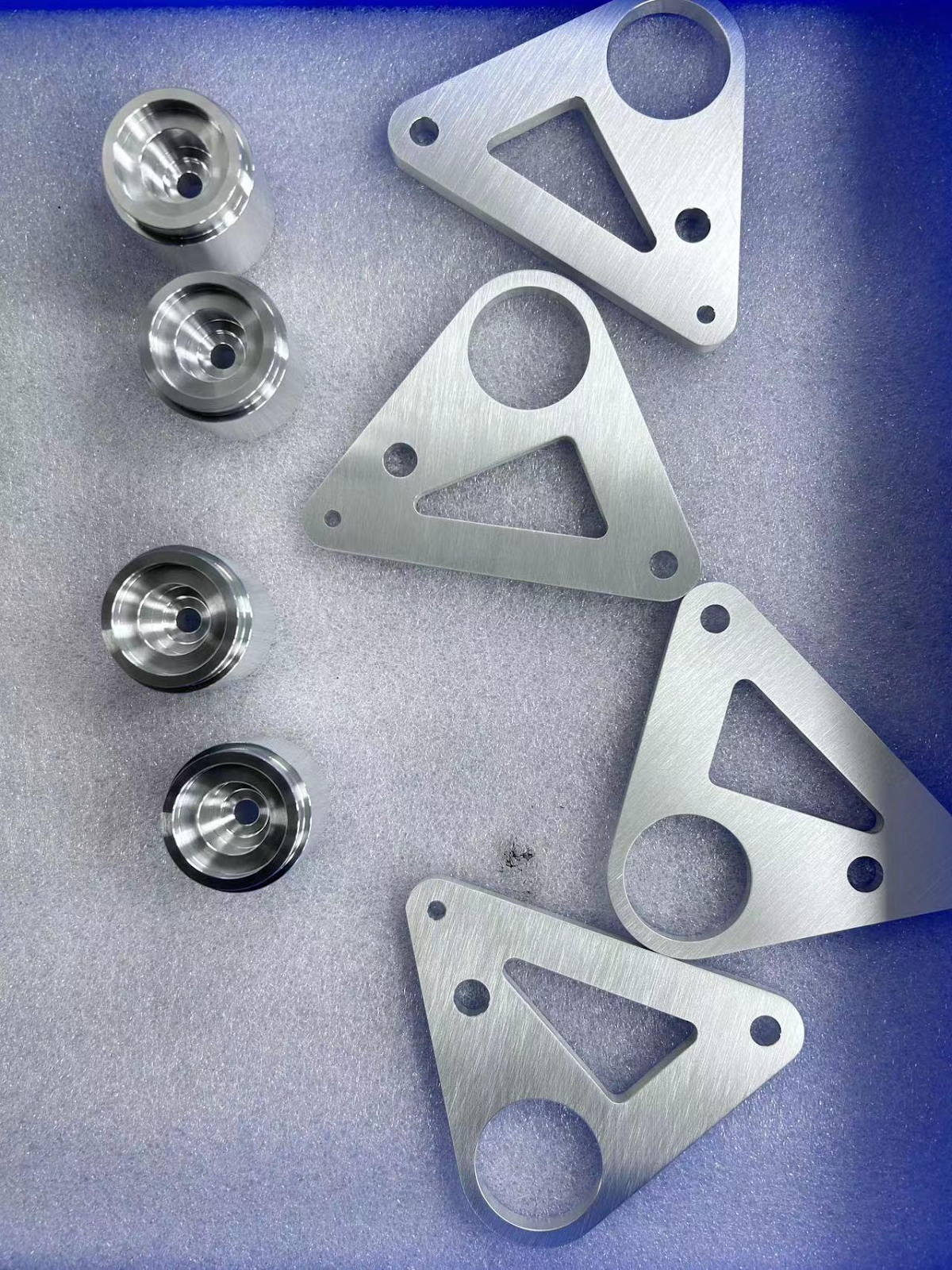
machined. The team has worked alongside the suspension team in the manufacture of the other components the
upright will have an interaction with. The team has received CNC’d bell cranks and spacers that are fundamental
to the suspension system. The team has also installed the sway bar and pushrod components into the chassis.
With all of these components installed and finished, the last step in the suspension geometry validation is to
install the uprights.
For the work period of March 24 - April 6, what is your team's plan for near term work?
What major milestones does the team hope to achieve in your work?
Since the team experienced yet another unexpected delay with machining, the team expects to have the finalized
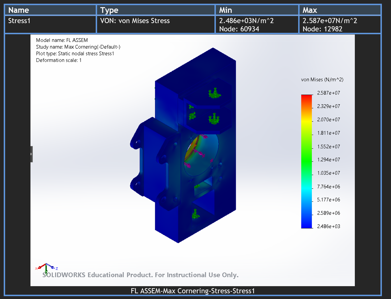
uprights by March 29. In the following week, the team will perform the force validation for both the front and rear
upright designs using the rig we have completed manufacturing in the past few weeks. Once the force validation is
completed , the team plans to start pressing the wheel bearings and wheel hubs into the uprights. These will be done
alongside the suspension geometry validation.
What obstacles does the team foresee in your project work over the next two weeks?
What solutions does the team have in mind and what back-up plans does the team have?
Due to the unexpected delay in the completed manufacture of the team’s uprights, the team is now officially behind
schedule. This puts pressure on the team to complete the validation in less time than originally allotted. To combat
this, the team has finalized all setups required to validate. This puts the team in a position to complete all validation
in less than three days when the uprights are received in order to have data for the technical report presentation.
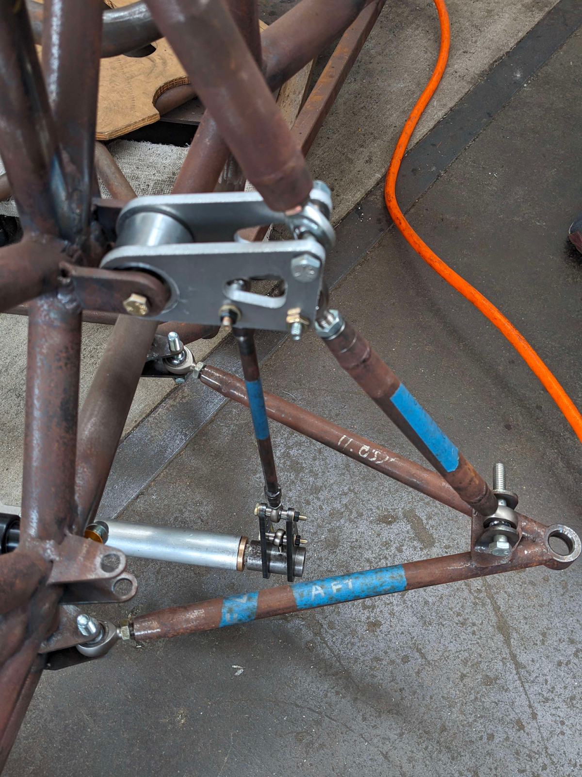
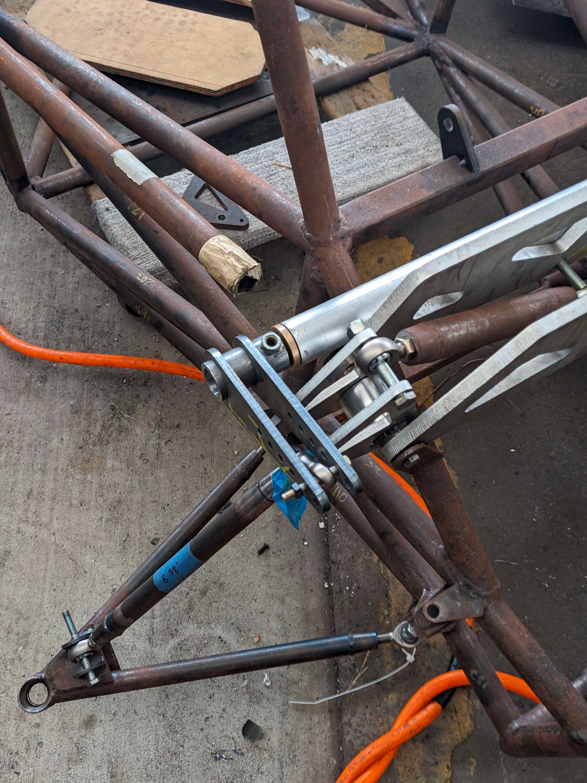
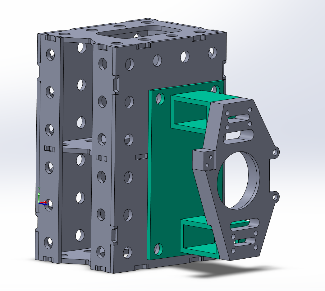
Figure 2: Rear Control Arm and Sway Bar Assembly
Comments
Post a Comment